
This was an initial experiment I ran back in December, to see if this idea might work.
The problem of using polarising filters
So, one thing I’ve been thinking about is how to get the orientation from the polarising filters from a side view. From above it is easy (although the 180 degree symmetry needs resolving) one just uses two cameras (with 0 and 45 degree polarising filters on) and a flat polarising filter on the back of the bee. From the side it’s more awkward – with a ridge etc…
Using Colours
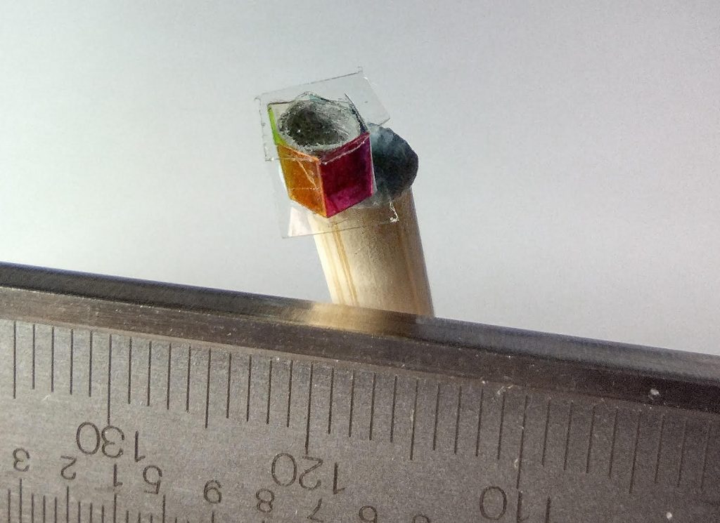
Anyway, I went back to my original idea of using colours. For this experiment I made a hexagonal ‘tube’ – it’s a little large in this case (about 5mm across, when I think 3mm is probably the limit – I made a smaller one yesterday about 3mm across that also worked). I put inside the glass-bead style retroreflector and cover the ends of the tube (maybe needs strengthening using superglue).
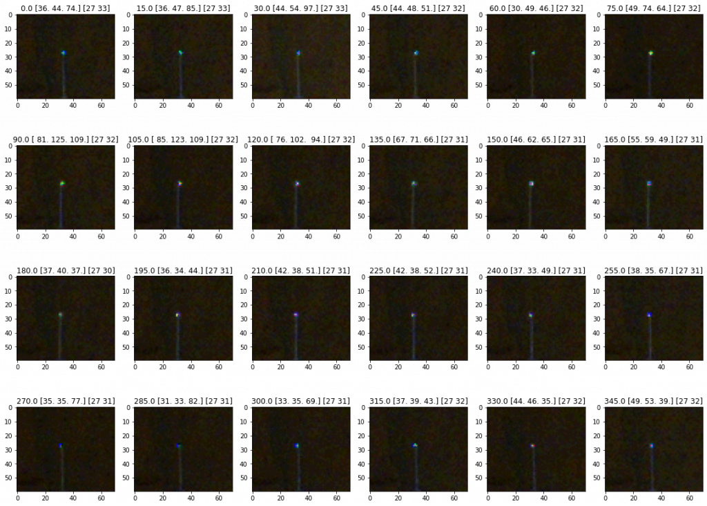
I then used a tracking system to take photos of the unit from 8m away (the longest straight line in my house :).
I think maybe this isn’t as bright as it used to be: the colour camera isn’t quite as sensitive, the filters absorb some light, and the cylindrical shape rather than a ridge means it’s also a bit weaker [although works from all angles], and I used one flash instead of four… but anyway, here’s some of the photos to give an idea…
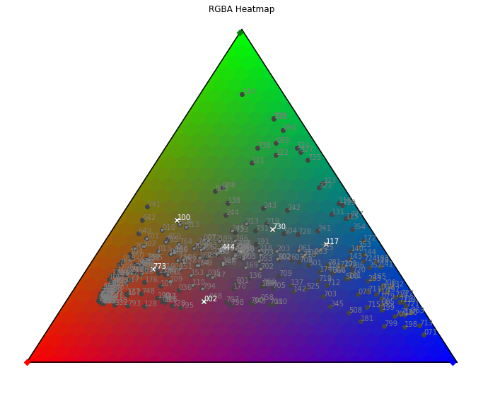
To build it I picked 6 filters using their spectra provided by LEE filters, hoping I’d pick some that would lead to a path that doesn’t have overlaps. I also just picked filters that transmitted the most light. This could be improved I think – as you can see the dots aren’t in a neat circle…
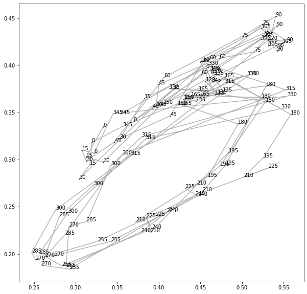
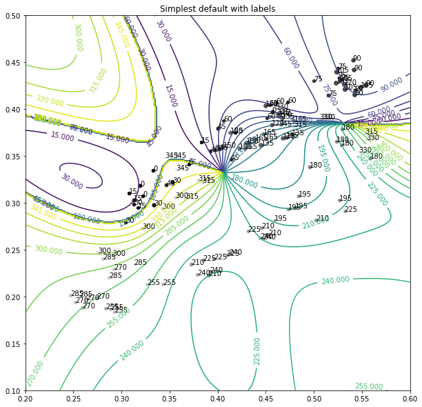
This on the same sort of triangle as above (although flipped and rotated, so the two axes represent normalised colour)… the numbers are roughly (+/- 15) the angle of the tag. The tag was imaged in order (0,15,30…345,0,15…) and the lines join sequential measurements. Currently we are just using the average value for each colour in a square around the tag, but in future this could be improved.
We can fit a Gaussian process (or other regressor to this)…
Cross Validation Results
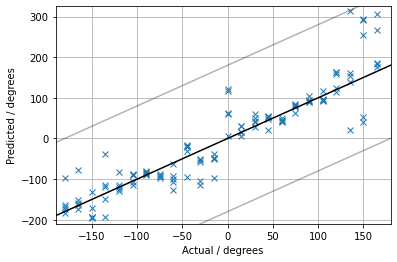
MAE = 31 degrees
RMSE = 48 degrees
(chance level is: MAE 90, RMSE 104).
You can see that there’s two directions that seem to look similar (-30 & 150 degrees) where it gets a bit confused. One can see why in the colour map plots (where the dots around 330ish and 150ish are a bit jumbled together – you might even be able to tell by eye looking at the initial photos in the second figure).
Tweaking the choice of colours should help, also taking more close together training points, rather than asking it to interpolate over 15 degree steps.
Note also the actual angle of the tag was only accurate to +/- 15 degrees.
Anyway – this colour-tag idea is another potential approach, instead of the polarising filters.
I only spent a couple of hours or so getting this together, so hopefully I can make a lot of improvements on this in the new year.